Thermal Overload Protection Formula
Motor Protection How To Calculate Thermal Overload Trip Time For Relay Youtube

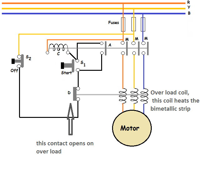
Thermal Overload Motor Relay Protection
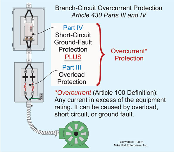
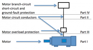
Motor Calculations Part 1 Motors And Branch Circuit Conductors Ec M

Protection Of Transformer Motor Generator Line Busbar Motor Protection
Thermal Overload Relay Working Principle Your Electrical Guide
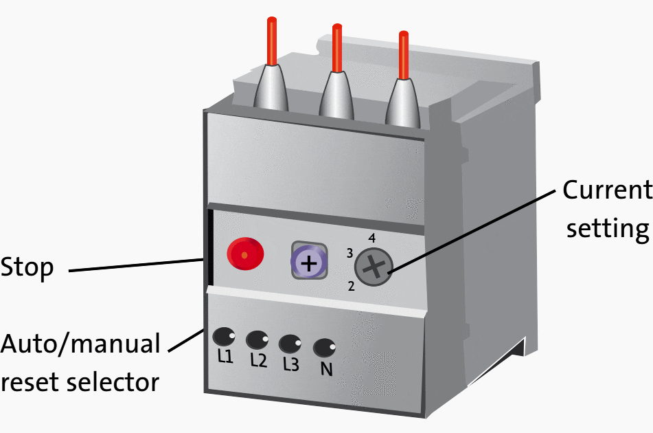
How To Know If You Set The Correct Current On A Motor Thermal Overload Relay Eep
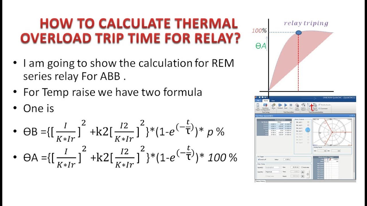
The fundamental equation 6 can be expressed in a simpler form.
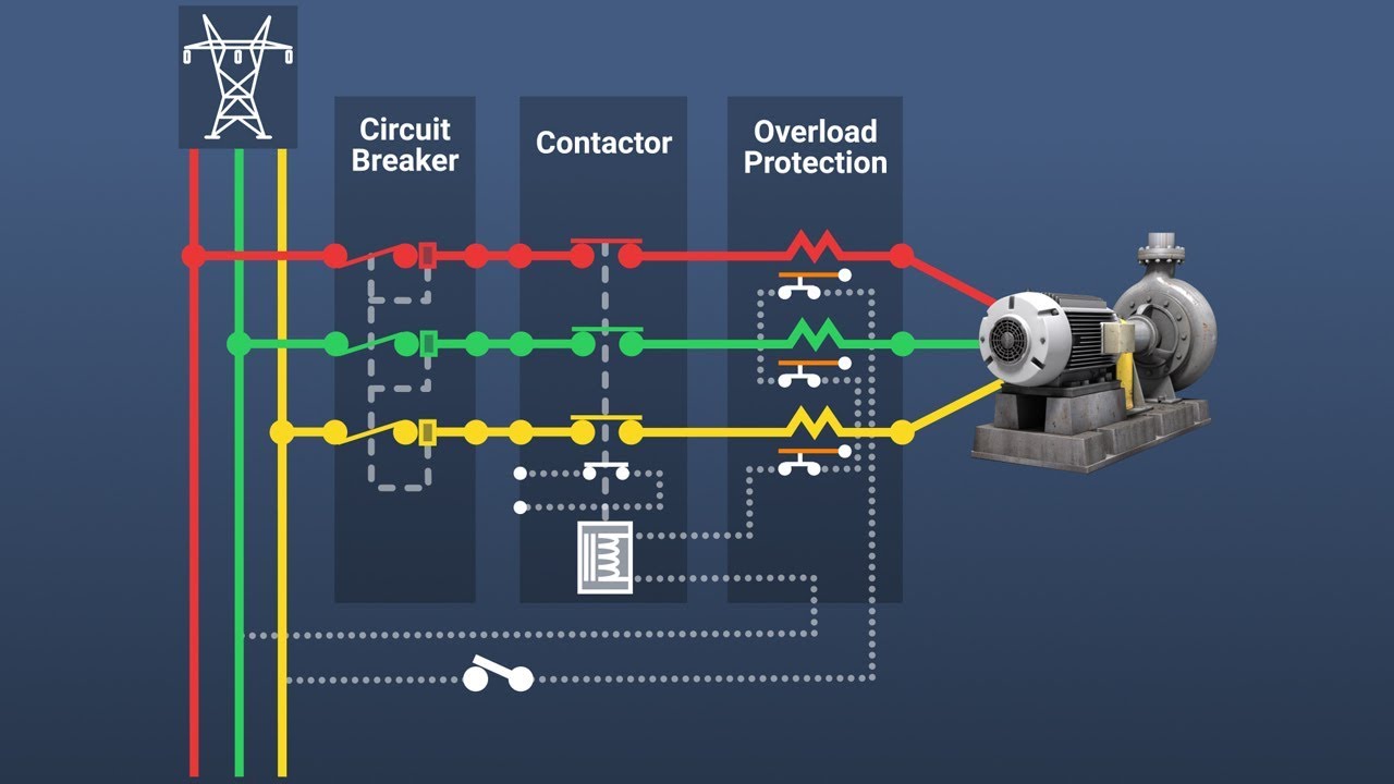
Thermal overload protection formula. This is the principle behind the thermal replica model of a motor used for overload protection. 40 ec and service factor. Electric motors are commonly rated for operation in an ambient temperature of 40 deg. Thermal overload protection is normally used in an alarm mode to notify system operators of the potential for cable damage.
The temperature t at any instant is given by. The thermal overload relay does not provide short circuit protection as it takes sufficient time to open the contacts. For understanding motor thermal overload protection in induction motor we can discuss the operating principle of three phase induction motor. C 104 deg.
Calculated sizing for overload device to provide overload protection to a 3 phase 200 volt 15 hp motor with full load ampere is 35 ampere ambient temp. τ t. Temperature rise is proportional to the current squared. Therefore this type of relay is used in conjunction with fuses to provide overload and short circuit protection to the circuit.
However thermal overload protection can be used to trip a circuit breaker as well. Answer ambient temp 40 ec. Basically to setting the overload value we refer to this formula. 35 ampere x 125 43 7 ampere 44 ampere.
Due to such symmetrical distribution when three phase power supply. Protection point 2500 kva 2500 kva ansi 17 6 x i fl x 58 16 6 x i fl x 58 inrush for 0 1 sec 8 x i fl 12 x i fl nec rule 6 x i fl 6 x i fl 6 x i fl time current curves transformers 29. If the motor in the example from step 2 had a service factor of 1 15 then its overload would be acceptable and the motor could be operated without damage. There is one cylindrical stator and a three phase winding is symmetrically distributed in the inner periphery of the stator.
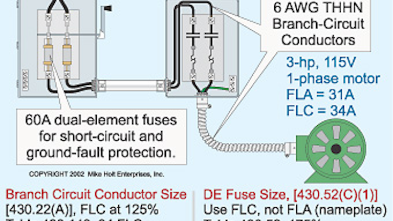
R r θ dt dθ r r 1 s i c m r 2 8 s τ c m r 9 let r r u θ 10 and dt d r r 1 dt du θ 11 therefore the first order thermal model equation becomes the simple form. 1 ib in iz ib anticipated operating current of the circuit iz current carrying capacity of conductor or cable or motor. U dt du i2 τ 12 the solution of the first order equation is.
Motor Calculations Part Iii The Motor Overload Jade Learning
Http Prorelay Tamu Edu Wp Content Uploads Sites 3 2017 04 The Necessity And Challenges Of Modeling And Coordinating Microprocessor Based Thermal Overload Functions For Device Protection 1 Pdf
Motor Overload Protection Youtube

Motor Thermal Overload Protection Electrical4u

Motors Motor Circuits And Controllers Part Ix Nec Article 430 Electrical Contractor Magazine
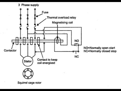
Sizing Of Contactor And Overload Relay For 3 Phase Dol Starter Youtube

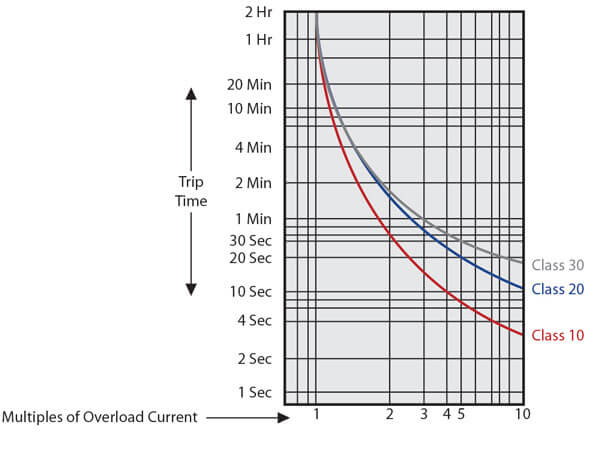
Iec60947 4 1 Tripping Time Curves As A Function Of Actual To Full Load Download Scientific Diagram

All Electrical Study Electrical Some Basics

Motors And The Nec Ec M
Motor Calculations Part 2 Feeders Ec M
Overload Relay What Is Overload Protection C3controls

Motor Protection Principles
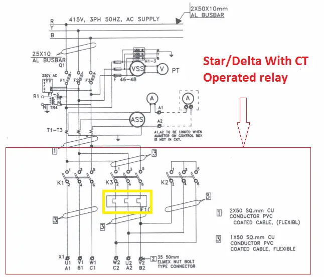
Ct Operated Thermal Over Load Relay Current Setting Calculation Electrical4u